The Fokker DR-1
Synopsis
At the start of World War I the airplane was looked upon, by the Generals of both sides, as being limited to locating the enemy troop concentrations and spotting for the artillery. An extension of the reconnaissance balloons. So successful was the airplane, in this role, that air combat grew out of the need to prevent the enemy reconnaissance aircraft from fulfilling its role and to protect ones own aircraft.
Most aircraft of the time were limited to clumsy two seat bi-planes with under powered and unreliable engines. Germany had the largest number of aircraft at the start of the war, 232, followed by Russia, 224, France, 138, and Britain with 113. None of the aircraft at the beginning of the war was officially intended for fighting. It was left up to the pilot or observer to take a pistol or rifle with him to take a shot at the enemy aircraft.
 The highest toll of downed
aircraft, initially, was not from other aircraft but from ground fire.
In fact both sides had a higher risk from being shot down by friendly fire
than they did by an enemy aircraft. This resulted in the development of
the identification markings that are so familiar with World War I aircraft.
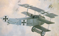
The German pilots liked to paint their aircraft in bright colors and patterns.
In fact, one of Von Richthofens Fokker Triplanes was a vivid scarlet red,
easily seen by the troops down below. As a result he became known as the
Red Baron.
The highest toll of downed
aircraft, initially, was not from other aircraft but from ground fire.
In fact both sides had a higher risk from being shot down by friendly fire
than they did by an enemy aircraft. This resulted in the development of
the identification markings that are so familiar with World War I aircraft.
The German pilots liked to paint their aircraft in bright colors and patterns.
In fact, one of Von Richthofens Fokker Triplanes was a vivid scarlet red,
easily seen by the troops down below. As a result he became known as the
Red Baron.
The first actual fight, in which an enemy aircraft was forced down, was by a British crew, armed with a rifle, forcing a German reconnaissance aircraft to land. This resulted in an escalation of conflicts with all sorts of weapons. It soon became apparent that the machine gun was the weapon of choice. The problem was that most aircraft, at the time, were not capable of carrying the added weight.
From about end of 1914, the race for air supremacy was on. First the French dominated with a machine gun mounted in front of the pilot, shooting forward through the propeller, a metal plate mounted on the back of the prop prevented the prop from being shot off. The Germans countered with an interrupter gear connected to the engine cam that would prevent the gun from firing as the prop came in front of the gun.
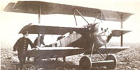
Each side fielded faster and more maneuverable aircraft. By 1917 the Germans were trying to counter the British Sopwith Triplane. The most famous of these was the Fokker DR-1. A total of 320 were built before production was stopped in 1918 This plane became famous in the hands of Germanys aces, Richthofen (80 victories), Ernst Udet (62 victories), Erich Loewinhardt (53 victories) and Werner Voss (48 victories).
It was powered by a 110 hp Oberursel or Le Rhone rotary engine. The armament was two Spandau machine guns. It had a top speed of 115 mph and a service ceiling of 19,600 ft.
Fokker DR-1 (number 425/17) was the airplane that Richthofen was killed in on April 21, 1918. He also flew several other DR-1s, 114/17, 127/17, 141/17, 152/17, 477/17, and 425/17.
The Fokker DR-1 was the original design of Reinhold Platz. It was a cantilever triplane with balanced ailerons and elevators. The wings were of great strength, with hollow box-spars, which were considerably light in weight. The wing spars were joined together to form a solid full-span spar. Initially there were no inter wing struts, but, in flight testing, a wing vibration developed so struts were added in the production version.
The wing ribs were of plywood with lightening holes and the leading-edges, as far back as the spar, were covered with thin plywood sheet tacked to the spar. The remainder of the wing was fabric-covered. The trailing-edges were of wire, which formed a scalloped profile when the fabric covering was doped.
Overhang portions were provided
to balance the ailerons, on the top wing only. The ailerons were framed
in steel tube and fabric covered. The middle wing had two cut-outs to
improve downward visibility. The bottom wings had small ash skids.
The welded steel-tubing fuselage
was braced by diagonal wires to make a rigid box girder structure. The
fuselage was fabric-covered including triangular plywood skins from the
cowling to just behind the cockpit, and plywood top decking. The
tail plane was a simplified triangular profile. The tail-plane, balanced
elevators and balanced rudder were framed in steel tubing. Two struts
braced the tail-plane from below.
 |
The center-section
and undercarriage were of steel streamlined tubing. The axle had a
large fairing, which provided extra lift. The wheels were sprung with
elastic shock cord. |
Building a Replica of the Fokker DR-1
In August of 1990 the Museum of Flying in Santa Monica California acquired the parts of a DR-1 replica. This consisted of the unfinished wings, fuselage frame, elevator assembly parts, and landing gear structure. Because of the unknown status of the hardware it was decided that the airplane would be restored as a static display. It was also decided that the final detailing and paint scheme would be of the DR-1, 152/17 that Manfred von Richthofens flew, instead of the typical Red DR-1, 425/17,that most people associate with the Red Baron.
In December 1990 the grand nephew of Richthofen visited the Museum and signed the left leading edge of the wing. During 1991 fittings for the wing attach and ailerons were fabricated and the assemblies temporarily attached to checkout the fit.
 |
 |
 |
|
Richthofen
Signature
|
Assembly
Checkout
|
Cowling
Mold
|
A foam mold was made for the fabrication of the fiberglass cowling. Numerous fittings had to be made and welded to the fuselage. Veneer wood sheets of plywood were cut and fitted to the lower landing gear wing and the forward fuselage. The landing gear V struts were fabricated and attached to the gear wing and axle. This assembly was then attached to the fuselage.
 |
 |
 |
|
Skinning
Gear Wing
|
Completed
Gear Wing
|
Welding
the Fuselage
|
By early 1992 most of the fabrication had been completed and covering of the structure was started. Polyester aircraft fabric was used instead of the traditional cloth used in 1917. After the fabric was glued onto the structure, the material tightened (shrunk) using heat and, in the case of the wing, stitched to the wing ribs using traditional methods. All fabric covered parts were doped and then coated with an aluminized dope to block out the ultra violet from the sun.
The next major task was the installation and fitting of the engine. A Le Rhone 9 cylinder rotary air cooled engine was selected. Prior to the installation of the engine, a firewall with supporting shaft was designed and attached to the fuselage. The engine had to be refurbished with new push rods, rocker arms, repaired intake tubes and bearings to support the engine. A propeller hub was machined to attach the wooden Curtis propeller.
Once the engine was mounted to the fuselage the rough fiberglass cowling was attached and fitted. Stiffeners were added internally to the cowling and the outer surface contoured and smoothed to fair into the fuselage.
|
Putting
on Wing Fabric
|
Installation
Complete
|
Heat
Shrinking
|
Motorcycle wheels were mounted to specially machined wheel hubs and attached to the landing gear assembly. Rolled metal wheel covers completed the landing gear.
The airplane was then disassembled
and masked for painting. The first step was to paint the insignias.
This was a two step process. First the black crosses were painted and
then the white. This was then masked and the red was sprayed , followed
by the green.
  |
 |
|
Fuselage
Fabric
|
Heat
Shrinking
|
Silver
Dope Applied
|
The airplane was assembled and the final phase of completing the cockpit was started. All cockpit components were built from sketches and drawings obtained from the research library at the Museum. The one exception were the two machine guns which were provided for the airplane. The control stick and rudder bar were connected to the control surfaces.
 |
 |
 |
|
Installing
Engine
|
Fitting
Cowling
|
Project
Team
|
All instrument faces were modified to reflect the German characters used during that time period. The control stick contained two independent switches that allowed the pilot to fire one or both of the machine guns at a time. He also had a finger throttle control on the stick. The manufactured compass was mounted near the floor on the right side. On the left side was the throttle and mixture control unit.
 |
  |
|
Masking
Insignia
|
Machine
Guns
|
Cockpit
|
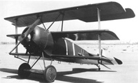
The airplane was completed
in August 1993 and moved to the Museum and put on display. In January
of 1994 the airplane was hung in the Museum where it is presently on display.
 |
Roll
Out in August of 1993
|
|
Hanging in the Museum of Flying Santa Monica, California |
 |